| Citation: |
Heng Wang, Zhenyu Pan. Performance optimization of thermoelectric devices and its dependence on materials properties[J]. Materials Lab, 2023, 2(1): 220053. doi: 10.54227/mlab.20220053

|
Performance optimization of thermoelectric devices and its dependence on materials properties
-
Abstract
In this perspective, we discuss the optimized performance of thermoelectric cooling devices and how it is affected by materials properties. The discussion is based on simulations using a numerical method with one dimensional transport equations and the concept of relative current density. The coefficient of performance (COP), representing the efficiency of a device, is of key importance such that when designing a new type of device, it is the parameter to be maximized, whereas others such as the cooling power, can be set by adjusting the dimensions of the design. The COP of a single stage device under a given temperature difference, is only determined by the materials’ figure of merit zT (or z) and the Seebeck coefficient α. While it is the higher the better for the former, the influence of α is complicated. While higher zTs are always preferred, materials with comparably high zT and very different α could be valuable in constructing graded legs that outperform uniform ones. Lastly, proper pairing of legs is important to ensure the materials properties are used to their full potential.
-
Keywords:
- Peltier devices /
- Relative current density /
- Uni-leg /
- Functional graded materials
-

-
Author Biography
 Heng Wang is an assistant professor at department of Mechanical, Materials and Aerospace Engineering, Illinois Institute of Technology. He received his PhD in materials science from California Institute of Technology. Before joining IIT he was a postdoctoral researcher at the Molecular Foundry, Lawrence Berkeley National Lab. His current research interests include high-performance thermoelectric materials, as well as rational device design and applications. In addition, he is particularly interested in the interplay of photoelectric and thermoelectric phenomena.
 -
References
1. L. E. Bell, Science, 2008, 321, 1457 2. T. C. Holgate, R. Bennett, T. Hammel, T. Caillat, S. Keyser and B. Sievers, J. Electron. Mater., 2015, 44, 1814 3. Global Thermoelectric Modules Market Size And Forecast To 2025, https://www.marketwatch.com/press-release/thermoelectric-modules-market-size-poised-to-touch-usd-7279-million-by-2025-2022-08-01, Accessed Sep. 2022. 4. G. J. Snyder, S. LeBlanc, D. Crane, H. Pangborn, C. E. Forest, A. Rattner, L. Borgsmiller and S. Priya, Joule, 2021, 5, 748 5. S. Hong, Y. Gu, J. K. Seo, J. Wang, P. Liu, Y. S. Meng, S. Xu and R. Chen, Science Advances, 2019, 5, eaaw0536 6. J. He and T. M. Tritt, Science, 2017, 357, eaak9997 7. G. J. Snyder, Thermoelectrics Handbook: Macro to Nano, CRC Press, America, 2006. 8. E. Müller, S. Walczak and W. Seifert, physica status solidi (a), 2006, 203, 2128 9. W. Seifert, G. J. Snyder, E. S. Toberer, C. Goupil, K. Zabrocki and E. Müller, physica status solidi (a), 2013, 210, 1407 10. W. Seifert and V. Pluschke, physica status solidi (b), 2014, 251, 1416 11. G. J. Snyder, E. S. Toberer, R. Khanna and W. Seifert, Physical Review B, 2012, 86, 045202 12. R. He, G. Schierning and K. Nielsch, Advanced Materials Technologies, 2018, 3, 1700256 13. K. Uemura, CRC Handbook of Thermoelectrics, CRC Press, America, 1995. 14. H. J. Goldsmid, Introduction to Thermoelectricity, Springer, Germany, 2010. 15. O. Owoyele, S. Ferguson and B. T. O’Connor, Applied Energy, 2015, 147, 184 16. U. Erturun, K. Erermis and K. Mossi, Applied Thermal Engineering, 2014, 73, 128 17. U. Erturun, K. Erermis and K. Mossi, Applied Energy, 2015, 159, 19 18. Y. Thimont and S. LeBlanc, Journal of Applied Physics, 2019, 126, 095101 19. S. Oki, K. O. Ito, S. Natsui and R. O. Suzuki, Journal of Electronic Materials, 2016, 45, 1358 20. Y. Wu, J. Yang, S. Chen and L. Zuo, Energy, 2018, 147, 672 21. M. Hong, W. Lyu, Y. Wang, J. Zou and Z. G. Chen, J. Am. Chem. Soc., 2020, 142, 2672 22. Z. Pan, R. Cui, X. Xiao and H. Wang, Materials Today Physics, 2021, 20, 100457 23. G. H. Kim, L. Shao, K. Zhang and K. P. Pipe, Nature Materials, 2013, 12, 719 24. L. Wang, Z. Zhang, Y. Liu, B. Wang, L. Fang, J. Qiu, K. Zhang and S. Wang, Nature Communications, 2018, 9, 3817 25. V. L. Kuznetsov, L. A. Kuznetsova, A. E. Kaliazin and D. M. Rowe, Journal of Materials Science, 2002, 37, 2893 26. Y. Gelbstein, Z. Dashevsky and M. P. Dariel, Physica B: Condensed Matter, 2007, 391, 256 27. W. Liu, K. C. Lukas, K. McEnaney, S. Lee, Q. Zhang, C. P. Opeil, G. Chen and Z. Ren, Energy & Environmental Science, 2013, 6, 552 28. E. Hazan, O. Ben-Yehuda, N. Madar and Y. Gelbstein, Advanced Energy Materials, 2015, 5, 1500272 29. Z. Bian, H. Wang, Q. Zhou and A. Shakouri, Physical Review B, 2007, 75, 245208 30. S. I. Kim, K. H. Lee, H. A. Mun, H. S. Kim, S. W. Hwang, J. W. Roh, D. J. Yang, W. H. Shin, X. S. Li, Y. H. Lee, G. J. Snyder and S. W. Kim, Science, 2015, 348, 109 31. Y. Lu, Y. Ding, Y. Qiu, K. Cai, Q. Yao, H. Song, L. Tong, J. He and L. Chen, ACS Applied Materials & Interfaces, 2019, 11, 12819 32. E. J. Bae, Y. H. Kang, K. S. Jang and S. Y. Cho, Scientific Reports, 2016, 6, 18805 33. H. Wang, J.-F. Li, M. Zou and T. Sui, Appl. Phys. Lett., 2008, 93, 202106 34. S. N. Zhang, T. J. Zhu, S. H. Yang, C. Yu and X. B. Zhao, Journal of Alloys and Compounds, 2010, 499, 215 35. G. Qiu, S. Huang, M. Segovia, P. K. Venuthurumilli, Y. Wang, W. Wu, X. Xu and P. D. Ye, Nano Letters, 2019, 19, 1955 -
Rights and permissions
This is an open access article under the terms of the Creative Commons Attribution License, which permits use, distribution and reproduction in any medium, provided the original work is properly cited.
Figures(11)
Tables(1)
Information
Article Metrics
Export File
Citation
Heng Wang, Zhenyu Pan. Performance optimization of thermoelectric devices and its dependence on materials properties[J]. Materials Lab, 2023, 2(1): 220053. doi: 10.54227/mlab.20220053
Format
Content
 DownLoad:
-
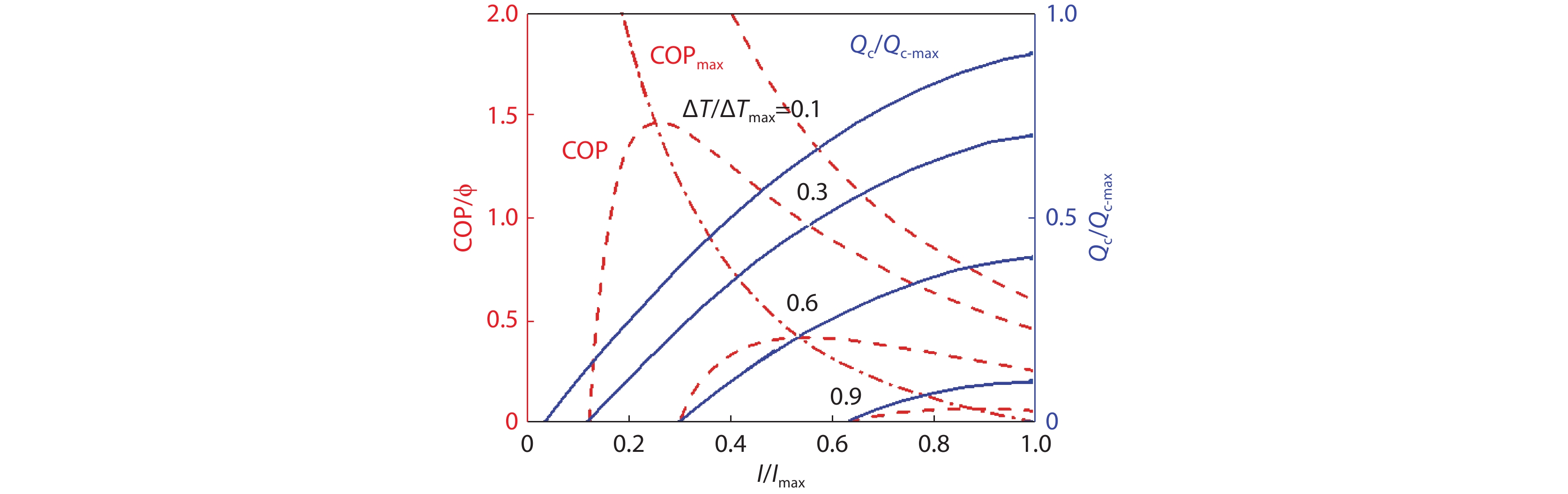
Figure 1.
Performance of a single stage commercial device as functions of relative operating current up to Imax.[22] Copyright 2022, Elsevier. The current corresponding to the maximum cooling power when ΔT = 0, Qc-max. Data are shown for four temperature differences across the device, relative to the maximum temperature difference it could maintain ΔTmax, 0.1, 0.3, 0.6, and 0.9. Red dashed curves are COPs. The solid, blue curves are cooling power Qc relative to Qc-max. The red dash-dot line connects the maximum COPs at different temperatures.
-
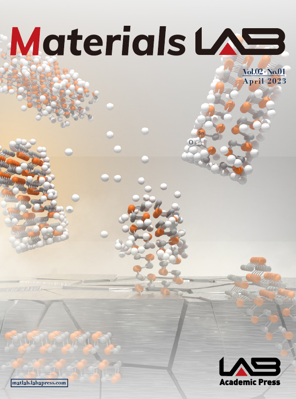
Figure 2.
Problem setup for analysis. The lengths of legs, as well as cross-sectional area are dimensional parameters. Arrows to the right define the vector directions.
-
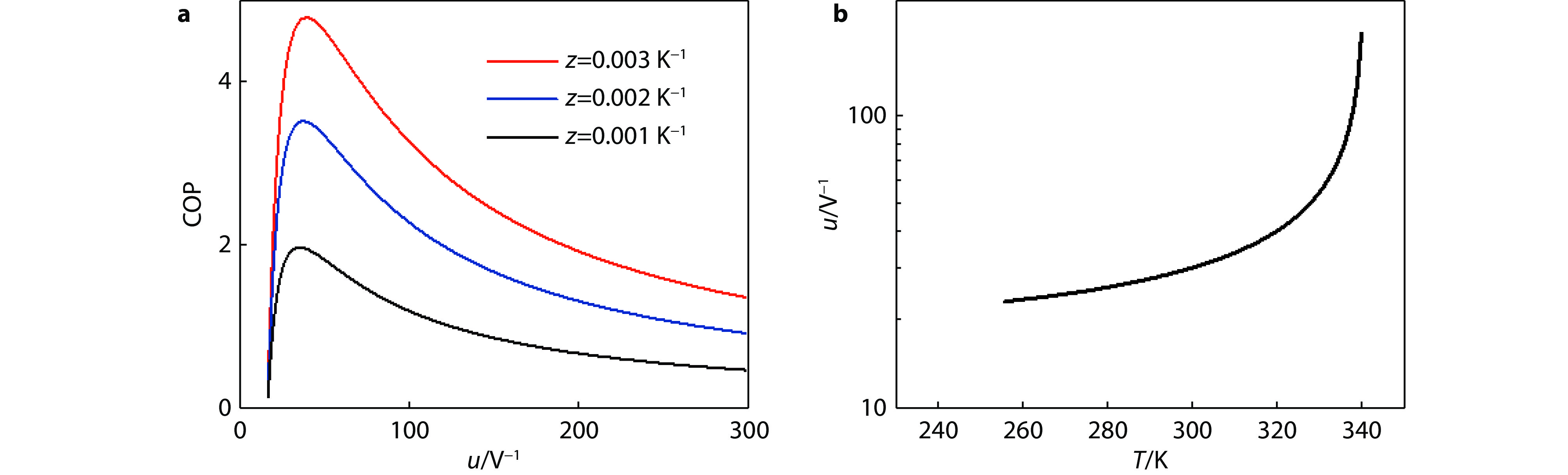
Figure 3.
a, COP as a function of u for materials with different z (assuming hot side temperature 300 K, ΔT =10 K, α = 200 μV/K). b, u across a p-leg made of commercial material working under maximum ΔT. Instead of position, u is plotted against temperature.
-
Figure 4.
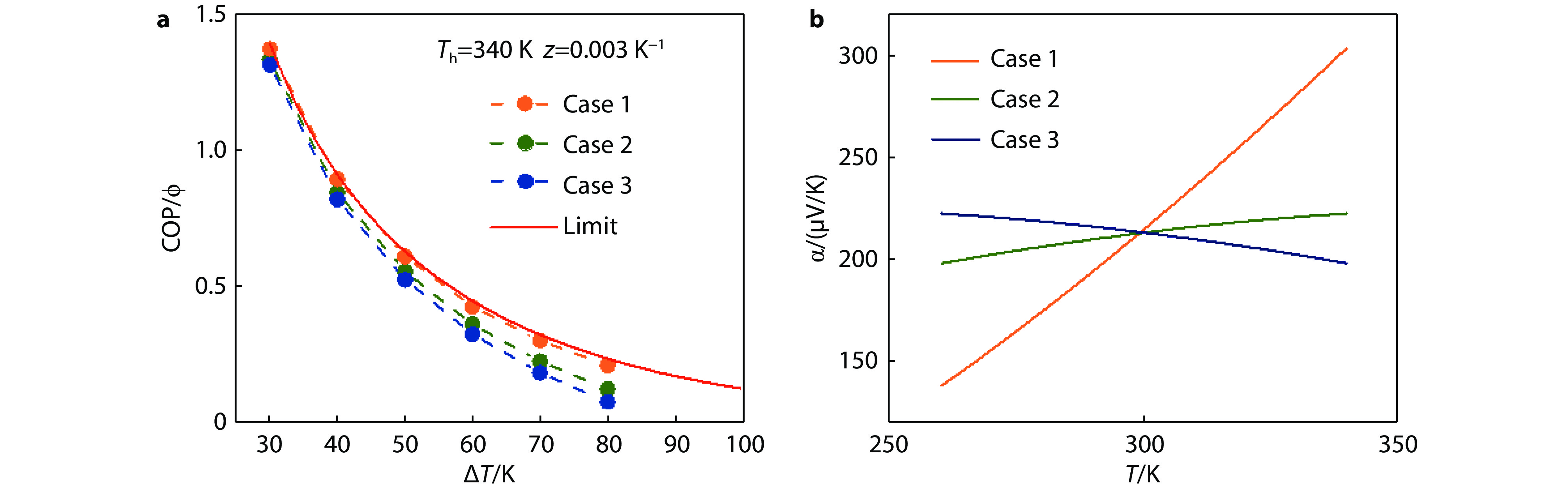
a, Maximum COP of a single leg for three hypothetical cases, all have the same constant z = 0.003 K−1. The limit COP is obtained when all segments along a leg could operate at the most efficient conditions. See more discussion in section 2.4. b, The temperature dependence of α for each case. Case 2 is the dependence of α in commercial p-type Bi2Te3 alloy.
-
Figure 5.
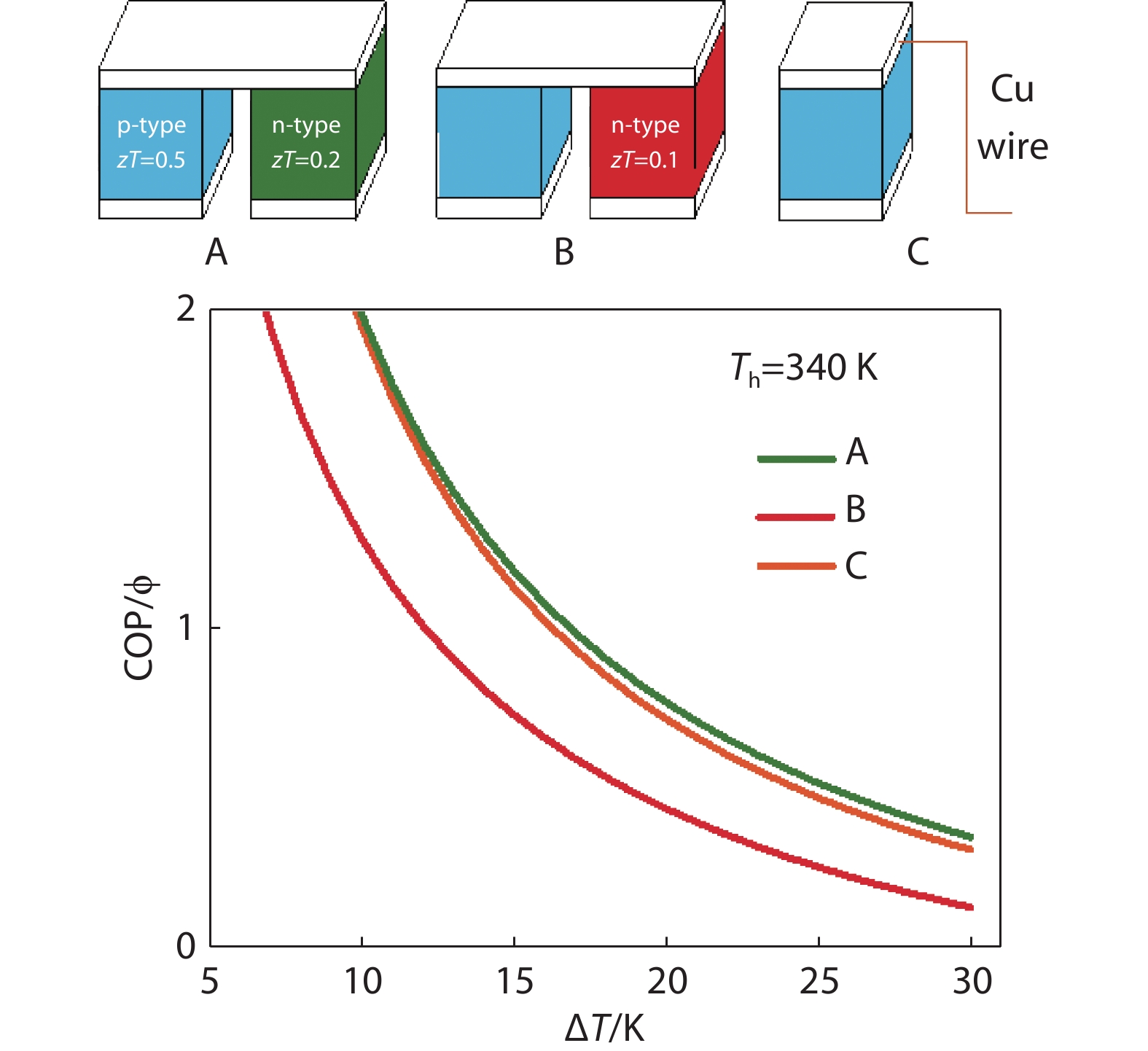
Optimized couple COP for three hypothetical cases. p-leg is a material using Bi0.5 Sb1.5Te3 properties except for thermal conductivity which is scaled to have zT = 0.5. n-legs are different materials based on Bi2Se0.3Te2.7 but scaled to have A: zT = 0.2, and B: zT = 0.1. C is an uni-leg design with Cu wire. Dimensions of legs are not to scale.
-
Figure 6.
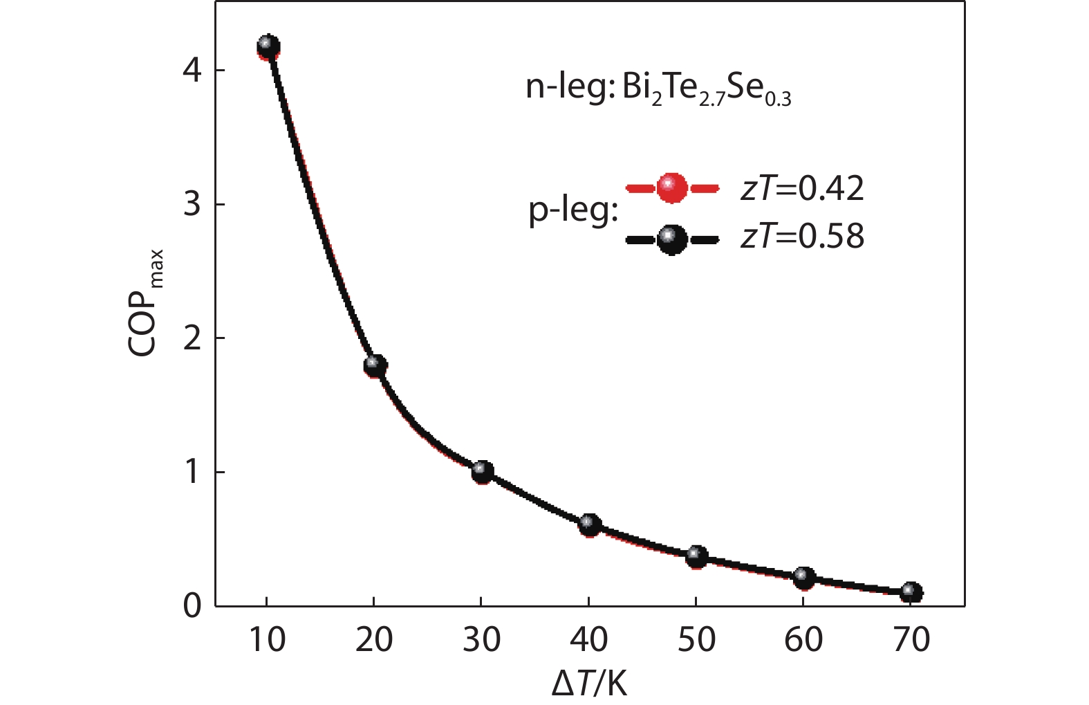
Maximum COP under different ΔT for two devices with p-legs made with a zT=0.42 and α=70 μV/ K, b zT=0.58 and α=170 μV/K.22 Copyright 2022, Elsevier.
-
Figure 7.
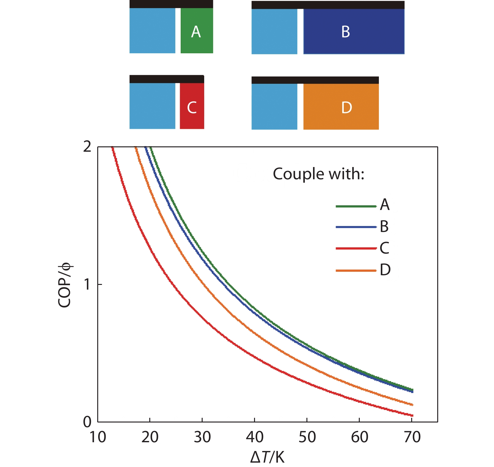
Optimized couple COP for four couples. p-legs (light blue) are commercial Bi2Te3 (see Fig. 4b); n-legs are: A, a hypothetical material with zT same as n-Bi2Te3, while α = −300 μV/K; B, same as A with α = −100 μV/K; C, a hypothetical material with zT half of commercial n-Bi2Te3, and α = −300 μV/K; D, same as C but α = −100 μV/K. The illustrations represent optimized cross-sectional area ratios assuming square or circular cross-sections.
-
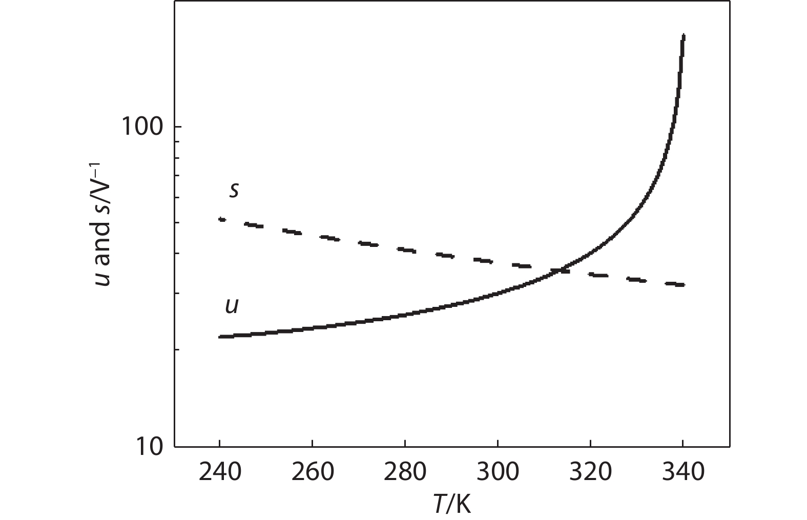
Figure 8.
u and s across a p-leg of commercial Bi2Te3 alloy operating under maximum ΔT with hot side temperature 340 K.
-
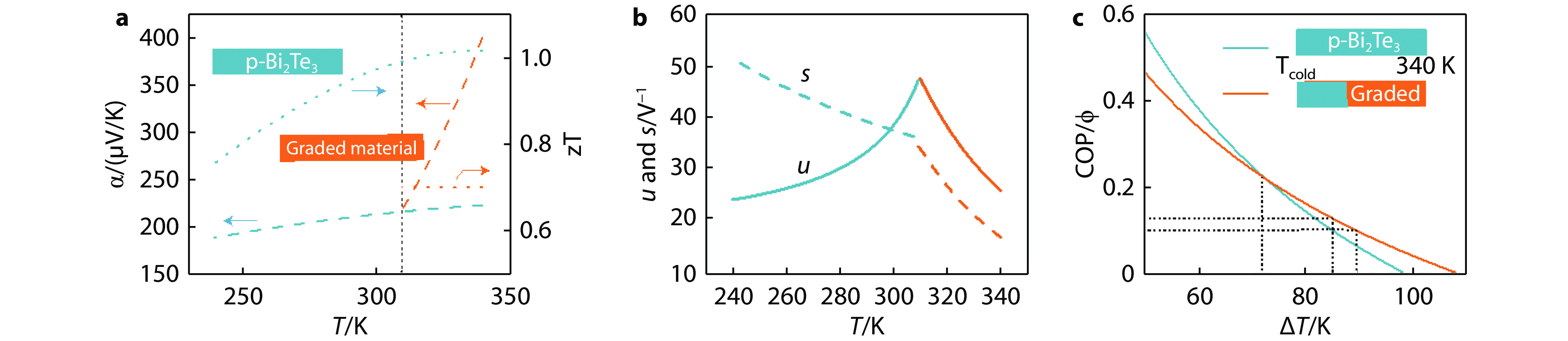
Figure 9.
Comparison of two leg designs: one is commercial (blue) and the other a hybrid with commercial material and a graded section. a, Seebeck coefficient α and zT as functions of temperature. b, The u and s profile in the hybrid design. c, Maximum COP as a function of ΔT.
-
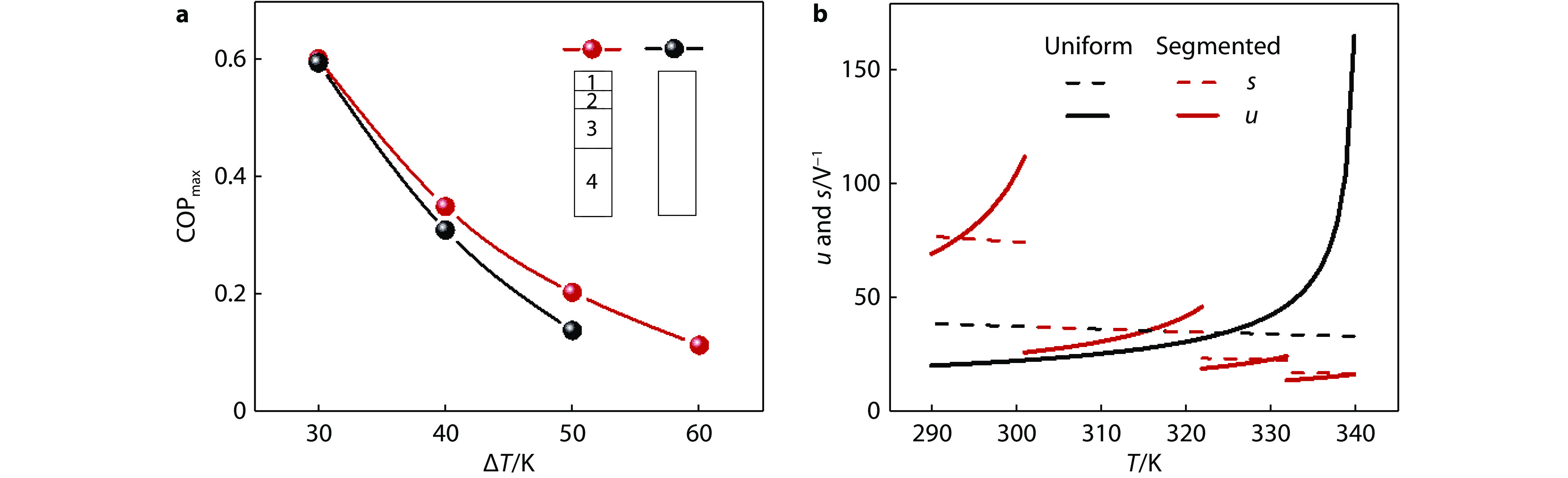
Figure 10.
a, Simulated performance of two devices with hot side at 340 K. One with a four-segmented p-leg (numbered 1 through 4 from the cold side to the hot side), and the other with a uniform p-leg. Relative length for each segment is illustrated. b, s and u in each device.